Non-Linear techniques

Linear techniques are widely used for pyramidal coding because they
are easy to analyze in the frequency domain. They are also efficient since
they can often be computed as separable convolutions. Nevertheless, restricting
ourselves to linear kernels seems to be a big limitation to our compression
scheme. Improvements in the compression ratios are most likely possible
by going to non-linear REDUCE and EXPAND functions. Thus, we have also
taken a look at the existing non-linear approaches and we tried to come
up with our own NL scheme.
Existing NL methods
Most NL methods we encountered are starting from the observation that linear
filters are doing a pretty bad job around edges due to the blurring. They
assumed a significant gain would be obtained by trying to preserve the
edges and details that are not part of high frequency periodic structures.
On the other hand, periodic structures should be eliminated from the images
since they give rise to aliasing errors in the decimated images. As linear
filtering makes it difficult to achieve high attenuation of aliasing components,
it seems NL filters are more adapted for the removal of unnecessary detail
information from decimated images.
-
In [5], morphological filters were used to generate image
pyramids. We did not investigate this technique because the paper said
this method introduces distortion and has poor noise properties, which
makes decimated images visually unpleasant.
-
In [8], filters based on the median operation were proposed
; the median is known to have good edge and detail preservation properties.
They made experiments with different types of filters, including MMF (Multi-Level
Median Filter), FMH (FIR-Median Hybrid Filter), and RPFMH (Recursive Predictive
FMH). We decided to implement the MMF scheme because it yields the best
results in terms of entropy of the error image.
The MMF decimation filter can be seen as a stack of median filters
applied to the horizontal, vertical and diagonal neighborhoods of the samples,
as shown on the figure. The reconstruction filter is using med{x1, x2,
x3, x4, z}, where x1 to x4 are the immediate neighbors of the sample and
z is the median of the diagonal averages and the 2x2 average.
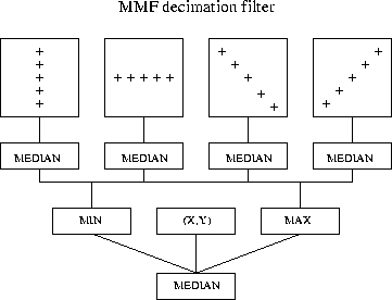
figure: MMF decimation filter diagram
-
In [9], a method for building anisotropic pyramids is introduced,
since isotropic filters are likely to lose or shift edges at lower resolutions.
The decimation filter relies on the solution of a diffusion differential
equation ; the interpolation filter uses a weighted mean of the horizontal
and vertical averages with weights depending on the angle of the local
intensity gradient. This way, blurring can be made orthogonal to edge lines,
enabling a high frequency detail removal while keeping the edges' information.
Due to the complexity of the decimation scheme, we decided not to implement
this method.
In the methods we reviewed, the design of the filters usually relies on
the intuition that improvements could be obtained on specific visual patterns
like edges. We felt that the choice of the EXPAND and
REDUCE
functions often seemed arbitrary, lacking some sort of general compression
efficiency analysis. In particular, many other factors have an impact on
the entropy of the difference images and are not even considered in these
papers. For instance, they give no proof that the EXPAND function
is optimized for the REDUCE function and
vice versa.
Optimal NL interpolation
If we choose a particular decimation filter, the problem can be reformulated
as follows :
-
Given an image I, compute its decimated image D = Reduce(I).
-
Divide I into four sub images (I1, I2, I3, I4) for even-even, odd-even,
even-odd and odd-odd pixels respectively.
-
Try to find the four optimal predictors Pi that predict Ii given D.
The subsequent Expand function is represented in the following diagram
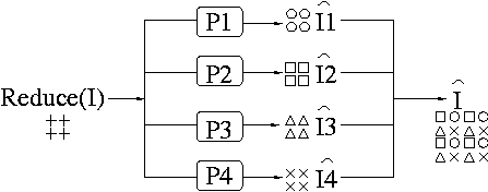
figure: Expand function using optimal non-linear predictors
An optimal NL predictor scheme exists theoretically. Indeed, if
we have sufficient information on the signal statistics, the optimal predictor
is shown to be the conditional expected value of the pixel given its neighborhood.

This is optimal in the sense that it minimizes the average
MSE
between images (with the given statistics) and their reconstructed counterparts
for a given neighborhood size. It is interesting to note that with a neighborhood
equal to the size of the image, this scheme becomes equivalent to storing
a table of all possible reduced and expanded images and simply doing a
look-up at interpolation time.
So why not using this for our interpolation filter ? The practical algorithm
would be :
- Tabulate the expected value for each neighborhood in a
preprocessing
step
- Use this as a look-up table to determine the interpolated pixel
values
from their neighborhood in the reduced image.
Unfortunately it is impossible to implement this method as is, because
of exponential memory requirements (the number of possible neighborhoods
is 256 to the power of the number of pixels in the neighborhood). Furthermore
we would need
very accurate signal statistics, since we are supposed
to compute the expected value of the intensity for each of these possible
neighborhoods. If we wanted to learn these statistics using a training
set, we would need a huge number of images, otherwise the look-up table
would be mainly made of holes and of non representative expected values.
Approximately optimal NL interpolation, 1st attempt
To alleviate these problems, we need to limit the number of different
neighborhoods to create the look-up table. This can
be done in several ways :
-
We could use very small windows, like 2 pixels large, yielding "only"
256^2 neighborhoods. The problem is that the scheme is likely to become
highly sub optimal compared to linear methods with big kernels, because
it is blind to the pixel information further than 1 pixel away.
-
We could quantize the values of the neighbors to a small number of levels
N, to get (N to the size of the window) cells, but this number is still
large, even when N is as small as 2 (65536 cells for a 4x4 neighborhood).
Furthermore, very different neighborhoods are likely to be put in the same
cell, so that the expected value might become meaningless.
-
We could compute a few characteristic features for the neighborhoods
and do the cell partitioning in the features' space. Thus the neighborhoods belonging to the same cell would have pretty close characteristic features.
Neighborhood features
We decided to implement that latter method because we thought that
some well chosen features would be more relevant to the choice of an interpolation
value. We used a 4x4 window
and considered various features, including :
-
The average intensity in the window
-
The (x,y) gradient at the center of the window
-
An edge detecting filter
-
A basic texture detecting filter
Feature quantization
Then the chosen features are quantized coarsely to get a reasonable
number of cells. With six 256x256 reduced images in our training set, we
thought we shouldn't exceed several thousands of cells in order to be able
to compute a meaningful expected value in each cell. Here is a reconstructed
image computed using features (1) and (2) with 8 levels of quantization for
each (mean, dx and dy). The visual result is pretty coarse, and it seems
obvious that we are far from an optimal interpolation.
Approximately optimal NL interpolation, 2d attempt
The problem of the latter interpolator is clearly a lack of adaptiveness
within each cell, since all pixels in a cell are mapped to a unique interpolation
value. Consequently, we propose to use an optimal linear predictor
instead of the expected value within each cell. Actually this is equivalent
to determining local best fitting planes. The resulting interpolator is
a piece-wise linear predictor with no continuity constraints on
the cell boundaries. We used the pixels of the window as input of the predictor
and the value in the sub image Ii as desired output. We didn't
use the features as inputs because they did not necessarily contain enough
information to make a good predictor. The interpolated image pixels
are computed as follows :

where S(x,y) is a vector containing the values of the pixels in
a window around (x,y). The coordinates of C are the coefficients of the
linear interpolator, and are computed for each cell and each sub image
using the correlation and auto correlation matrices of S and I as follows
:

Choice of a Reduce function
The implementation of this method requires to make numerous choices,
including the Reduce function to be used as a starting point. Nevertheless
there is no way to decide which decimation method is optimal, since the
error image variance gives a quality measure of the Reduce and the Expand
function dependently. The most relevant criterion will therefore be the visual
quality of the reduced image, including blurring, blockiness, and aliasing.
This makes sense because reduced images are likely to be displayed as is,
in a progressive transmission scheme for example. For this reason, we chose
to use the Optimal Cubic Reduce function that yielded the best visual
results.
Partitioning the images
Other choices include the window size, the features to characterize the
neighborhoods and the quantization method. There is a trade-off as for the size of the
cells. They have to be small enough
to have a good linear approximation (because of the low variance in the
neighborhood types). On the other hand, they have to be big enough to allow a good generalization
of the predictor to new images. In general, the optimal size will depend
on the location of the cell in the features' space (it will be easier to
fit a linear predictor for areas with small gradients for example).
We would have liked to do a thorough investigation of the different
possibilities, but considering the number of parameters to be chosen and
the time it takes to do a single learning procedure, we realized this was a rather
overwhelming task, at least in the context of a class project. Thus, we
restricted ourselves to a few experiment including the following :
Experiment 1
-
Optimal Cubic reduce function
-
4x4 window
-
Gradient and Average Intensity features
-
Non uniform quantization with 8 levels (8x8x8 cells)
-
Training set = { 'man', 'elaine', 'bridge', 'airfield', 'peppers', 'harbour'
}
-
Test set = { 'lena' }
We got a error image with variance 17.95, which is pretty good compared
to our best linear scheme that yielded 18.79 with the Optimal Cubic method
and
a 15x15 kernel.
Experiment 2
-
We changed the quantization to 10 levels for the gradient coordinates
and for the average intensity (10*10*4 cells)
Everything else unchanged, this modification enabled us to decrease the
first level error image variance to 17.48. We tried increasing the number
of cells by doing finer quantization but we could not get better results
than with the latter setup.
Experiment 3
-
We considered extending the local linear optimization by adding
to the neighbor values' some non linear inputs like the max, min and medians
of the intensities in the window : S, min{S}, max{S}, median{S} => Ii(x,y)
Sadly, it does not bring any improvement. It does better on the training
set (which makes sense because we added degrees of freedom), but it
probably lacks of generality and the variance increases to 24.7.
Previous (Linear techniques)-Next
(Non-Linear techniques(2))
