
 |
 |
 |
 |
 |
 |
 |
 |
 |
 When
high-resolution measurements are required it is strongly recommended
to allow the complete system to reach a stable temperature before
starting to collect data. This should include allowing the sample
temperature to be the same as the mounting plate.
Note:
Time can be saved by storing future samples within the instrument
enclosure ready for use.
Mechanical Aligning

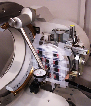
The sample should be positioned on the diffractometer axis using the Z movement of the sample cradle.
 For
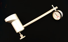
most applications this can be done mechanically using the dial gauge
supplied.
Aligning using x-rays can be done if:
the application requires data collection at very low angles of incidence so the sample has to be positioned that it exactly intercepts the incident beam when set parallel to it.
it is undesirable to make mechanical contact with the surface of a sample (e.g. partially processed semiconductor wafer, soft matter, powder, etc.).
Aligning Using X-rays
In order to align the sample using x-rays, the sample must be large and flat. The alignment procedure is as follows:
Mount a non-offset incident beam PreFIX module (e.g. a fixed or programmable divergence slit) and report this to the data collector software.
Center the sample in the center of the goniometer. You can use the dial gauge as an indicator of the center.
Set all axes: Z, 2Q, W, F and Y to "0" and make sure that the direct x-ray beam is not obstructed by the sample or MRD cradle.
Insert 0.2 mm Cu attenuation foil into the incident beam path in order to protect detector.
Perform 2q scan through the 2q = 0o position using small receiving slit to find the peak position of the direct beam. Make note of the 2q peak position.
Use Data Collector to recalibrate the 2q = 0o position to coinside with the peak position of the direct beam. Make a note of the peak intensity Ip.
Set 2q = 0o and move the sample with small increments of Z until the direct beam intensity is equal to Ip/2.
Make a small w scan and note the maximum intensity Im.
The next action depends on whether Im > Ip/2, or Im < Ip/2.
If Im > Ip/2, move the sample forward with small increments of Z until the maximum intensity measured in w scan, Im, equals Ip/2.
If Im < Ip/2, move the sample backwards with small increments of Z until the maximum intensity measured in w scan, Im, equals Ip/2.
Move the goniometer to the peak position of the w-scan where Im equals Ip/2 and make a note of Full Width at Half Maximum (FWHM) of the peak.
Measure the FWHM of the peaks in a series of w-scans with the y angle changing in steps of 0.5o around the starting position.
Set the y angle at the value that produces the minimum FWHM. (Alternatively, you can also automatically optimize the y setting in a series of w scans using the optimize program in the data collector software).
Move w to the peak position and recalibrate the w = 0o position using the data collector. The sample is now aligned at optimal 2q, w, y and z settings.