
EE368C Project Report
Mar. 12, 2000
Sangoh Jeong <sojeong@stanford.edu>
ˇˇ
Abstract
The conundrum in today's video communication system is to achieve the robustness of compressed video data in error-prone environment. And a variety of techniques are being tackled not only in academia but also in industry. However, due to the innate vulnerability of compressed video data to the transmission errors, it doesn't seem that the reliable video communication in error-prone environment is so near-at-hand. And the goal of this project is to propose a new coding mode (Leaky-Inter mode) in hybrid video codec in order to get some robustness in error-prone environment, instead of losing a little coding efficiency in error-free environment. Theoretically, the new coding mode utilizes the leaky prediction which is known to improve error resiliency with only a small degradation by using a temporal prediction coefficient slightly less than one. In the experiment, the rate-distortion based control scheme was implemented on top of the basic H.263 video encoder structure to optimize the mode selection among the encoding modes including the new coding mode.
Table of Contents
1. Introduction
2. Video Compression
3. Coding Control
4. Error Propagation and Leaky Prediction
5. Proposed Method
6. Experiments and Results
7. Conclusion and Future Work
8. References
1. Introduction
In recent years, as people's interest in video communication system grows, a variety of techniques are getting merged to realize such a system. Among them, robustness in video transmission through error-prone environment is considered one of the hardest things to get in video communication technology. Since, generally, video data require high compression in which both spatial and temporal redundancy are used to reduce the amount of data, becoming vulnerable to even a little loss of it. Especially, it is well known that the prediction loop used to reduce temporal redundancy contributes to the propagation of errors[1]-[3].
In this project, a new coding mode is introduced to improve the error resiliency, besides the existing two types of modes of coding (INTRA, INTER). Since the new coding mode exploits the leaky prediction[1][4] to reduce the error propagation, it is named 'Leaky-INTER (L-INTER)' mode. This mode considers the propagation of prediction errors due to the transmission error when the encoder predict the next frame if there is some kind of feedback information from the decoder. Hence, this project can be thought of as a kind of joint source and channel coding in the sense that the encoder takes into account the channel condition when it selects a coding mode. Further, rate-distortion optimized mode selection[5][6] is also applied to choose the best coding mode among the new coding mode and the two existing coding modes. By using the reconstructed frame containing transmission errors to predict the next frame as the third coding mode, the encoder will have another degree of freedom to achieve better performance in the context of rate-distortion. Estimating the overall distortion of decoded frame due to not only quantization error, but also error propagation can enhance the robustness of video coders to the transmission error.
The proposed method requires one extra frame memory and modification of the encoder decisions, and it
is applied to standard video codec H.263[7]. In the experiment, much of the work will be focused on the error-robustness
of the new encoding scheme. But, for the purpose of comparison, the experiment
under the two-mode-only control scheme will precede in the first hand. H.263
(TMN-8) codec software[8] was modified to accommodate the rate-distortion
optimization for the coding modes including the L-INTER mode. For
convenience, the pattern of the errors used in the experiment was assumed to
be 3 consecutive GOBs (Group Of Blocks) losses. Finally, it is assumed that the encoder
has exact knowledge of the mismatch between decoder reconstruction and encoder
reconstruction for the feedback cases. This information will mainly influence the mode decission between the INTRA, INTER, and
L_INTER modes for the assumed feedback information.
2. Video Compression
2.1 Data Units
Although the terminology and concept to be introduced here came from H.263 standard[7], they are predominant nowadays. For the popular video format QCIF(Quarter Common Intermediate Format), details are explained. Each picture is divided into groups of blocks (GOBs) and a group of blocks (GOB) comprises of 16 lines. The number of GOBs per picture is 9 for QCIF. The GOB numbering is done by use of vertical scan of the GOBs, starting with the upper GOB (number 0) and ending with the lower GOB. An example of the arrangement of GOBs in a picture is given for the QCIF picture format in Figure 1. Each GOB consists of 11 macroblocks (MB). Each GOB is divided intoMBs. A MB relates to 16 pixels by 16 lines of Y (luminance) and the spatially corresponding 8 pixels by 8 lines of Cb and Cr (Chrominances). Further, a MB consists of four luminance blocks and the two spatially corresponding color difference blocks.
Figure 1. Configuration of data in a QCIF picture
2.2 Fundamentals of Compression
Since video data consists of a time-ordered sequence of pictures, it requires a large amount of data that needs to be compressed. If we take a QCIF resolution which is equal to 176 X 144 for example, its raw source data rate amounts to more than 6 Mbit/s[5]. However, the current capacity of major transmission channel is far below than that and video data should be compressed.
Video compression could be achieved by simply compressing each frame with an image coding scheme such as JPEG standard. The most common 'baseline' JPEG scheme consists of breaking up the image into equal-size blocks. These blocks are transformed by a discrete cosine transform (DCT), and the DCT coefficient are then quantized and transmitted using variable-length code (VLC)s. This kind of coding is called INTRA frame coding, since the picture is coded without referring to other pictures in the video sequence.
However, more compression in video coding can be attained by taking advantage of the large amount of temporal redundancy. And such a technique that uses the temporal redundancy to attain the compression is called INTER frame coding. Usually, much of the depicted scene is essentially just repeated in every picture without any significant change. It is obvious that the video can be represented more efficiently by coding only the changes in the video content, rather than coding each entire picture repeatedly. This ability to use the temporal redundancy to improve coding efficiency is what fundamentally distinguishes video compression from still-image compression. Hence, the most successful class of video compression design is to utilize both the spatial and temporal redundancy in order to reduce a large amount of data. And the hybrid video codec (coder and decoder) such as Figure. 2 satisfies this condition.


Figure 2: General Hybrid Video Codec
When the encoder operates in INTRA mode, the original input image goes thorough DCT (Discrete Cosine Transform) and Q (Quantization) and variable length coded (VLC). In the Figure 1. VLC and VLD (Variable Length Decoding) are excluded. And the decoder decodes the bitstream with the INTRA mode, which means the compressed bitstream becomes the original image if it goes through VLD, IQ (Inverse Quantizer), and IDCT. But if the encoder operates in INTER mode, the every MB in the original input image is compared to the previously reconstructed frame which was stored in Frame Memory and the Motion Estimation (ME) is performed to find the motion vector (MV) which could be used for best motion compensation (MC). And the prediction error (Pe), the difference between the original MB and the motion-compensated MB, is encoded to compensate for the disparity between the original MB and the motion-compensated MB. Then, the MV and the encoded Pe are sent to the decoder to make the next INTER frame. The decoder uses the MV and the encoded Pe to reconstruct the original image in the INTER mode. Detailed operation of the hybrid codec is explained well in [5].
3. Coding Control
3.1 Low Complexity Control
The search for the
motion vector is made with integer pixel displacement in the Y component.
The comparisons are made between the incoming MB and the displaced MB
in the previous reconstructed picture.
If a full search is used, the search area
is up to ˇľ15 pixels in horizontal and vertical
direction around the original MB position. And the SAD (Sum of Absolute
Difference) is used as a criterion to find the best MV (Motion Vector) for
the MB[9].
![]()
For the zero vector, SAD(0,0)
is reduced by 100 to favor the zero vector when there is no significant
difference.
![]()
The (x,y) pair resulting in the
lowest SAD is chosen as the integer pixel motion vector, MV0. The corresponding SAD is
SAD(x,y).
After the integer pixel
motion estimation the coder makes a decision on whether to use INTRA or
INTER prediction in the coding. In the
traditional way, The following parameters are calculated to make the
INTRA/INTER decision:
![]()
![]()
INTRA mode is chosen if:
![]()
Notice that if SAD(0,0) is used,
this is the value that is already reduced by 100 above. If
INTRA mode is chosen, no further operations are necessary for the motion
search. If INTER mode is chosen the motion search continues with half-pixel
search around the MV0 position.
2.2 High Complexity Control (Rate-Distortion Optimized Control)
The problem of optimum bit
allocation to the motion vectors and the residual coding in any hybrid video
coder is a non-separable problem requiring a high amount of computation. To
circumvent this joint optimization, the problem is generally divided into two parts:
motion estimation and mode decision, i.e., the motion estimation for the INTER mode is
conducted first, and then given these motion vectors, the overall
rate-distortion costs for all considered MB modes are computed for
the rate-constrained mode decision. The overall procedure is also described
in [9]
. Here, only the rate-constrained mode decision is introduced.
All MBs are coded given the
mode decisions made for the past MBs. Rate-constrained mode decision
refers to the minimization of the following Lagrangian functional
![]()
![]()
and QP
is the quantizer being selected
for that MB. Note that the UNCODED
mode refers to the INTER
mode when the COD bit is set to ˇ°1ˇ± in H.263 standard. The term
SSD
stands for the sum of the squared differences between the original block s and its reconstruction.
![]()
and R (MODE, QP)
is the number of bits
associated with choosing MODE and
QP
including the bits for the
MB header, the motion, and all six DCT blocks. s' (i, j, MODE, QP) relates to the reconstructed
luminance values corresponding to s (i, j). We choose
![]()
where QP is the macroblock quantization
parameter. This relationship has been established by means of experimental
results[9]. And, from the relationships above, the coding mode which
minimizes the cost function J
4. Error Propagation and Leaky Prediction
4.1 Error Propagation
When errors happen at the decoder, it is known that the errors propagate spatially and temporally[1][3]. The recursive structure of the decoder which is used in the INTER mode caused the propagation of errors when they happen. Since the previously decoded frame is used as a reference for the prediction of the current frame in the INTER mode, the errors remaining after concealment therefore propagate to successive frames and remain visible for a long small[1]. In the Figure 4., effects for the typical transmission error of the loss of one GOB in frame 4[1]. The error propagates both in temporal and spatial way due to motion-compensated prediction.

Figure 4. Spatio-temporal error propagation
4.2 Leaky Prediction
Leaky prediction is known to
reduce the propagation of errors to subsequent frames at the cost of less
prediction gain[1][4]. The robustness of
the Differential Pulse Code Modulation (DPCM) systems is gained by attenuating the energy of the
prediction signal. Theoretically, INTRA coding can be considered as an extreme form of leaky prediction, where the prediction signal is completely attenuated. By using the INTRA mode for a certain percentage of the coded sequence, it is also possible to adjust the average attenuation. However, leaky prediction is a more general scheme that provides additional
flexibility. Furthermore, leaky prediction is not explicitly supported by existing standards for improved error resilience. Because the attenuation is applied in each time step, the energy of
superimposed errors decays over time and is finally reduced to a negligible
amount[1].
The underlying effect plays an important role in interframe error propagation of current video codecs, because leakage is introduced as a side-effect by spatial filtering in the motion-compensated predictor. H.263 and all recent video compression standards employ bilinear interpolation
for sub-pixel motion compensation, which acts as a low-pass filter. As
low-pass
filtering attenuates the high spatial frequency components of the prediction signal, leakage is introduced in the prediction loop. While error
recovery is also improved at the same time, this is really a side-effect, and the leakage
in the DPCM loop of standardized video codecs by itself is not strong enough for
error robustness[1]. For this purpose, additional leakage, such as more severe
low-pass filtering could be introduced. Although this would reduce coding
effiency, the trade-off between coding efficiency and error resilience may be more advantageous than for
INTRA coding because of increased flexibility in the design of the loop
filter. Considering the standardized H.263 syntax, the possible influence on the spatial
loop filer and the leakage in the prediction loop is limited, especially when operating
in the baseline mode. Because the amount of leakage in H.263 is too small to be useful for error resilience,
other techniques are needed to limit interframe error propagation. The most common
approach is the regular INTRA update of
image regions[1].
The systematic way to get the optimal value of the leaky
prediction coefficient which controls the leakage is described in [5]. It
introduces the temporal correlation coefficient to find a formal way to
reach the optimal value of the leaky prediction coefficient, but is is not
verified yet.
5. Proposed Method
5.1 The Leaky-Inter Mode
In this project, a
new coding mode other than two coding modes (INTRA, INTER) is introduced.
The new coding mode acts similar to the INTER mode, basically. But its range
of variance changes according to the value of the leaky prediction
coefficient ![]() .
In the Figure 5, the relationship between the prediction error (pe) and
the leaky prediction coefficient
.
In the Figure 5, the relationship between the prediction error (pe) and
the leaky prediction coefficient ![]() .
.
Figure 5. Operation of the Leaky-Inter Mode
Here, MB1 is the
macroblock in the original frame and MB2
is the motion-compensated macroblock from the previously reconstructed
frame. The prediction error (pe) is similar to that of the existing
INTER mode. In fact, when ![]() = 1, the Leaky-Inter mode acts exactly the same as the Inter mode. And, when
= 1, the Leaky-Inter mode acts exactly the same as the Inter mode. And, when
![]() = 0, it acts in
the same way the INTRA mode does. By introducing this new mode to the
encoder and using the rate-distortion based mode selection scheme, the
encoder got to acquire another degree of freedom in choosing the best mode
for specific situation. But, main purpose of this new mode is to use the
leaky prediction to increase the error resiliency when errors happen at the
decoder.
= 0, it acts in
the same way the INTRA mode does. By introducing this new mode to the
encoder and using the rate-distortion based mode selection scheme, the
encoder got to acquire another degree of freedom in choosing the best mode
for specific situation. But, main purpose of this new mode is to use the
leaky prediction to increase the error resiliency when errors happen at the
decoder.
5.2 The Rate-Distortion Optimization for selection of the optimal coding mode
The Lagrangian cost function for each mode is calculated separately. But, in this project, the quantization parameter (QP) is considered to be fixed when the cost function is calculated. The the new coding mode is appended as another choice, and the uncoded mode is not considered to be a separate mode but a part of the INTER and of the Leaky-INTER mode. The cost function for each mode and the decision process for the best selection of the coding mode is described in the following Figure 6. The decision step is applied to all three modes in the same way except for the last step that determines the best mode.
Figure 6. The calculation of cost function and the decision process
6. Experiments and Results
6.1 The setup of the encoder
In order to find the effect of
the new coding mode, the encoder introduced in Figure 2. was modified to
accommodate and simulate the erroneous bitstream. The following Figure 7.
shows the encoder structure that was used in this project. It is basically not
different from the H.263 encoder except for the Frame Memory 2 and the leaky
prediction coefficient ![]() .
To be exact, H.263
(TMN-8) codec software[8] was modified to realize the rate-distortion
optimization. Then it was used for the optimal selection of the coding mode
among the three modes including the L-INTER mode in several
environments. In the figure 7., ME implies Motion Estimation, MC means
Motion Compensation and MD is for Mode Decision.
.
To be exact, H.263
(TMN-8) codec software[8] was modified to realize the rate-distortion
optimization. Then it was used for the optimal selection of the coding mode
among the three modes including the L-INTER mode in several
environments. In the figure 7., ME implies Motion Estimation, MC means
Motion Compensation and MD is for Mode Decision.

Figure 7. The setup of the encoder used in the experiment
ˇˇ
6.2 Conditions on experiments
The pattern of the errors used in the experiment was assumed to be 3 consecutive GOBs (Group Of Blocks) losses, and the position of 3-GOB losses were assumed to be random in a frame. Further, the percentage of GOB losses for the entire frames was set to 6.67 %, and it was achieved in the following way. First the random frame numbers which would have 3-GOB losses were generated keeping the loss percentage for the entire frames. Then, the position of the 3 GOBs was determined. But the position of errors was the same in each experiment in order to compare the results in different environments. And it is assumed that the encoder has exact knowledge of the mismatch between decoder reconstruction and encoder reconstruction for the feedback cases in order to influence the mode decision among the INTRA, INTER, and L-INTER modes. For all experiments, the previous frame concealment was used to conceal the errors when the GOB losses happen and the 'foreman' sequence was used as a test sequence. The experiments were done for four cases. Two of them are aiming at finding the pure effect of the L-INTER mode and the others are aiming at finding the influence of the new coding mode in the rate-distortion based optimal selection when there is feedback information.
6.3 Results
6.3.1 Effect of the L-INTER MODE
In order to find the pure effect of the Leaky-INTER mode, two tests were executed In both cases, it was assumed that there is no feedback information about the decoder status and the rate control was done through changing the quantization parameter (QP). The Figure 8. shows the effect of L-INTER mode in error-free environment.
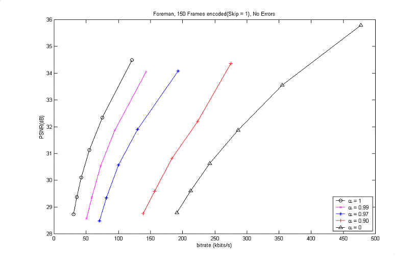
Figure 8. Coding performance of RD optimization of the 2 modes (INTRA, L-INTER) without errors
The above results came from the
rate-distortion optimization of the 2 coding modes (INTRA, L-INTER) for
several values of the leaky prediction coefficient
![]() .
When
.
When
![]() = 0, it its
obvious that the coding is performed only with the INTRA. And, when
= 0, it its
obvious that the coding is performed only with the INTRA. And, when
![]() = 1, the graph
coincides with that of the traditional coding with 2 modes (INTER, INTRA).
It is also sure that the rate-distortion curve is very sensitive to the
value of
= 1, the graph
coincides with that of the traditional coding with 2 modes (INTER, INTRA).
It is also sure that the rate-distortion curve is very sensitive to the
value of
![]() , especially when
it is between 0.9 and 1.0. When
, especially when
it is between 0.9 and 1.0. When
![]() = 0.99,
there was about 1.5 dB loss and when
= 0.99,
there was about 1.5 dB loss and when
![]() = 0.97, there
was about 3 dB loss in PSNR in comparison with the coding of traditional 2
modes. This implies that the L-INTER mode decreases the coding efficiency in
error-free case.
= 0.97, there
was about 3 dB loss in PSNR in comparison with the coding of traditional 2
modes. This implies that the L-INTER mode decreases the coding efficiency in
error-free case.
It's worthwhile to look at the
other result in case errors happen and there is no information available
about the decoder. The result for this situation is depicted in the
following Figure 9.
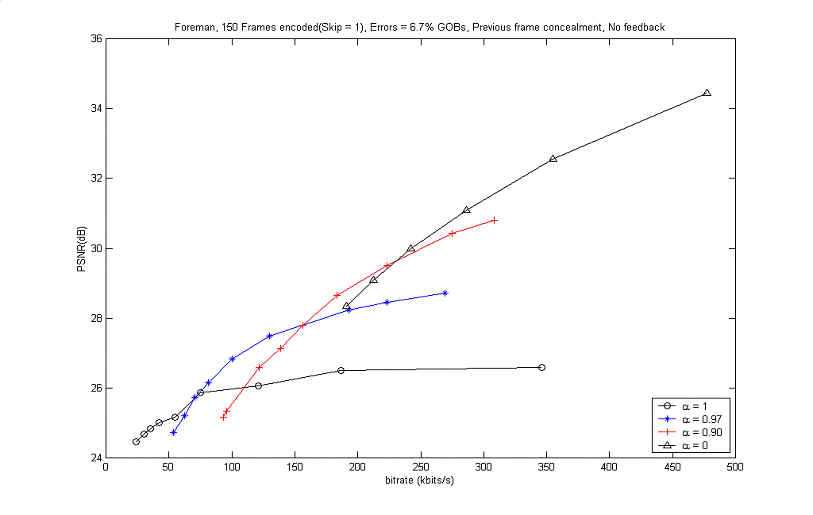
Figure 9. Coding performance of RD optimization of the 2 modes (INTRA,
L-INTER) with errors
The above results also shows
the performance of the
rate-distortion optimization of the 2 coding modes (INTRA, L-INTER) for
several values of the leaky prediction coefficient
![]() . However, in this
case, it is assumed that errors described in 6.2 happened and were concealed
instantaneously from the previously decoded frame. Again, when
. However, in this
case, it is assumed that errors described in 6.2 happened and were concealed
instantaneously from the previously decoded frame. Again, when
![]() = 0, it
indicates that the coding is performed only with the INTRA. And, when
= 0, it
indicates that the coding is performed only with the INTRA. And, when
![]() = 1, the graph
shows the result of the traditional coding with 2 modes (INTER, INTRA). As
the bitrate goes higher, there were significant PSNR gains for each graph
with different
= 1, the graph
shows the result of the traditional coding with 2 modes (INTER, INTRA). As
the bitrate goes higher, there were significant PSNR gains for each graph
with different
![]() . When
. When
![]() = 0.97,
there was about 1 dB gain at the bitrate of 125 kbits/s and 2 dB at 250
kbits/s in comparison with the coding of traditional 2
modes. This implies that the L-INTER mode increases the error resiliency in
error-prone
= 0.97,
there was about 1 dB gain at the bitrate of 125 kbits/s and 2 dB at 250
kbits/s in comparison with the coding of traditional 2
modes. This implies that the L-INTER mode increases the error resiliency in
error-prone
There were phenomena that cross-cuts among
graphs happened at specific bitrate for each ![]() .
It is considered to imply the limit point of rate-distortion curve that a
graph with a specific
.
It is considered to imply the limit point of rate-distortion curve that a
graph with a specific ![]() can show the error-resiliency with no feedback information. It is also
supposed that, as the quantizer gets coarser for the L-INTER and INTRA
operation, the loss of information due to quantization overwhelms the PSNR
gain due to the leaky prediction.
can show the error-resiliency with no feedback information. It is also
supposed that, as the quantizer gets coarser for the L-INTER and INTRA
operation, the loss of information due to quantization overwhelms the PSNR
gain due to the leaky prediction.
6.3.2 Rate-distortion based coding control with feedback cases
In this part, two experiments are aiming at finding the influence of the new coding mode in the rate-distortion based optimal selection when there is feedback information. The detailed description was also introduced in 6.2. Here, the experiments assume that the encoder has exact knowledge of the mismatch between decoder reconstruction and encoder reconstruction with the help of feedback information. The first case, when the encoder do not use the mismatch in Motion Estimation (ME) but use in Mode Decision (MD) and in Motion Compensation (MC). The result for this situation is shown in Figure 10. It compares the traditional two-mode (INTER, INTRA) control and the 3-mode control when errors happen.
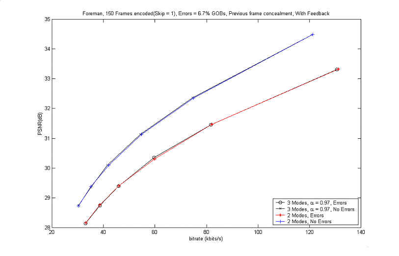
Figure 10. Comparison of coding performances of RD optimization of the 2 modes
and 3 modes with errors ˇˇ
when the encoder doesn't do ME, does MD and MC
with the feedback information
From the figure above, it's hard
to find the gain resulting from using the 3 modes including the L-INTER. There
could be several reasons for that. One possible reason is that delay factor
was not considered in this experiment. Since the exact concealment for errors
was done without any delay, the errors could not have time to propagate
especially in the 'foreman' sequence which has less motion in the first half
part. Another possible is that the experiment was done for the lower bitrate
which showed unfavorable characteristics in the Figure 9.
In
the last experiment, the encoder did not use the mismatch information in
ME and in MD but used it in MC. And, since the MD is not used for the
optimal selection of the coding mode, the encoder forced the erroneous region
to be encoded with L-INTER mode. The result for this situation is shown in Figure
11.
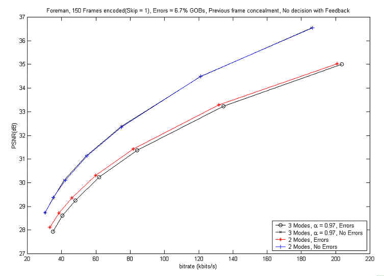
Figure 11. Comparison of coding performances of RD optimization of the 2 modes
and 3 modes with errors ˇˇ
when the encoder doesn't do ME, does MD and MC
with the feedback information
From the above result, we can suppose that it is less efficient to forcefully use the L-INTER mode for the erroneous region without RD based decision for optimal coding mode when there is feedback information. ˇˇ
7. Conclusion and Future Work
From the results, we have found that the proposed Leaky-INTER mode has much potential to be used for robust video transmission. The new coding mode showed emphatic error-resiliency in the situation of no feedback information depending on the value of the leaky prediction coefficient. In many real situation which has no feedback to the encoder from the decoder, this will be very useful. But, at least in this experiment scenario, it was not quite fruitful to prove the error-resiliency when there is information about the mismatch between the encoder and the decoder. Possibly, it comes from the fact that the situation of feedback assumed in this experiment is different from the reality. Since it assumes no delay in the feedback loop.
For future work, this experiment should be done to many video sequences with various error patterns. Especially, elaborated feedback scenario will find out the exact behavior of the leaky prediction. And the rate-distortion based coding scheme should consider more variables such as quantization parameter and the skipped mode. Finally, it will be very important to find the best leaky prediction coefficient in methodical way.
8. References
[1] B. Girod and N. Färber, "Wireless Video", in A. Reibman, M.-T. Sun (eds.), Compressed Video over Networks, Marcel Dekker, 2000.
[2] E. Steinbach, N. Färber, and B. Girod, "Standard
Compatible Extension of H.263 for Robust Video Transmission in Mobile
Environments"," IEEE Transactions on Circuits and Systems
for Video Technology , vol. 7, no. 6, pp. 872-881, Dec. 1997.
[3] B. Girod and N. Färber :
"Feedback-Based Error Control for Mobile Video Transmission",
Proceedings of the IEEE, special issue on video for mobile multimedia, Vol.
97, No. 10, pp. 1707-1723, Oct. 1999.
[4] A. Fuldseth and T. A. Ramstad, "Robust
subband video coding with leaky prediction in Proc. DSP Workshop,
pp. 57-60., Loen, Norway, Sept. 1996.
[5] G. J. Sullivan and T. Wiegand, "Rate-Distortion Optimization for Video Compression",
IEEE Signal Processing Magazine, November 1998.
[6] R. Zhang, S. L. Regunathan and K. Rose, "Video Coding with Optimal Inter/Intra-Mode Switching for Packet Loss Resilience",
IEEE Journal of Selected Areas in Communications, Vol. 18, NO. 6, June 2000, pp.
131-144.
[7] ITU-T Recommendation H.263, ˇ°Video coding for low bit rate
communication,ˇ±, 1998.
[8] Telenor H.263 Codec, ftp://dspftp.ee.ubc.ca/pub/tmn/ver-3.2/
[9] Video
Codec Test Model, Near-Term, Version 9~11 (TMN9~11) :
ftp//standard.pictel.com/video-site/h263plus/.